Background
This is a continuation of http://donsthings.blogspot.com/2017/06/k40-flyback-autopsy.html. In the previous post both myself and +Nate Caine tore down High Voltage Transformers (HVT) as part of our quest for knowledge of the details of the K40 LPS internals.
In this tear down the potting material was removed chemically in hopes that the circuit and its components could be kept in tack. The transformer was also sectioned a means of understanding its design.
In this tear down the potting material was removed chemically in hopes that the circuit and its components could be kept in tack. The transformer was also sectioned a means of understanding its design.
Donate:
Please consider donating (button to the right of this post).Your donations help fund additional research, tools and parts that I will return to the community as information.
The schematics for the LPS:
Removing the Potting
The potting was mostly removed using paint stripper. Caution: use gloves as this stuff is caustic.
 |
| Use gloves and eye protection this stuff is caustic |
 |
| HVT submerged in glass container |
The potting removal took nearly 2 weeks of repeatedly checking and refreshing the solution. The potting will come off in flakes which I washed off with each refresh. Unfortunately the stripper de-laminated the capacitors and destroyed their covering so no labels were visible. The diodes had no labels.
It is probably worth experimenting with other chemicals that might work faster and not destroy the components coating but this worked good enough to get the information we needed.
Discovering the Circuit
The component connections were carefully observed as the potting removal proceeded. This version (and it seems there are more than one) used 2 HV diodes and 2 HV capacitors in a Voltage Doubler configuration. In this case (unlike the previous autopsy) there were no parallel diodes.
 |
| Circuit removed from the potting. Overlay showing connection of secondary. |
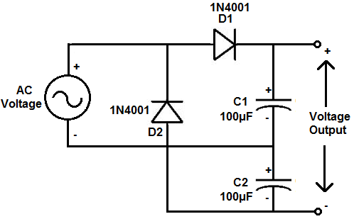 |
| Example circuit. These exact components are not what is used in a K40 LPS |
HVT Cross Section and Analysis
After the potting removal step the transformer was sectioned with an abrasive metal blade on a Dremel and then polished on a marble flat plate with 600 grit wet paper until the wire cross sections was visible.
 |
| Left: five section secondary. Right one section primary winding's |
Primary Winding
The primary winding consists of 40 turns of 21 wire bundles.
 |
| Primary winding |
Secondary Winding
The secondary winding consists of 5 sections of +400 turns wired in series.
 |
| Primary winding connection leads |
 |
| One section of secondary winding |
HVT Design
The HVT consists of a primary winding and a 5 section set of secondary winding's.
HVT Primary
The HVT primary has 40 turns in which each turn is a twisted set of 21 wires. The primary effective wire size indicates that the primary is designed to handle much more current than the secondary.
HVT Secondary
The secondary has 5 winding sections insulated from each other but connected in series.
The turns wound on three different secondary sections were counted, one on the first HVT and 2 from the second HVT. The first count = 499 and the two sections counted on the second HVT = 452 and 471 respectively.
I don't think the difference in the counts are caused by counting errors. Its seems that the turns on each section are not the same (Rt). I did not further investigate this variance in turn counts as I do not think it will materially change the outcome of the analysis.
Turns Ratio
Using an average of the last HVT 2 sections turns count lets assume:
- Average turns per secondary section = 461.2
- Number of secondary segments = 5
Total # of turns = 461.2 * 5 = 2306 total turns on the secondary
Therefore the HVT is a 40t to 2306t HVT transformer, a ratio of 1:57.65
Estimating Output Voltage
The voltage at the output can be expressed as:
Hv = Pv * Rt * Mv
where:
- Hv is the output voltage
- Pv is the voltage on the primary
- Rt is the ratio of primary to secondary
- Mv is the voltage multiplication factor
Therefore for every 100V on the primary the output = :
Hv = Pv * Rt * Mv
11,300 = 100 * 57.65 * 2
Calculating HVT Primary Voltage
The typical K40 PS output voltage is specified at 23,000V @20ma.
If we solve the above equation for Pv:
Pv = Hv/(Rt*Mv)
And use it to estimate the primary voltage at spec:
Pv = 23000/(57.65*2)
Pv = 200 Volts
By inspection of the LPS schematic I estimate the HV buss to run at about 240-300 volts, 40 volts larger than the estimate above..
This error of 40 volts on the primary equates to about 2,306 volts on the output or 10% of the specified output. This error can easily be the result of an error in estimating the total turns across the 5 secondary sections [perhaps each secondary section has different turns] or simply differences in any given manufactures specified HV output.
Primary Current Estimates:
The specified max current output for a typical K40 supply is 20ma. In a transformer the voltage on the output is increased by the turns ratio. So to the current in the primary is larger than the current in the secondary by that same ratio (Rt).
Therefore:
Pi = Si * Rt
where;
Pi = the primary current
Si = the secondary current
Rt = the turns ratio
Solving for the primary current using K40 LPS specs and given the output current = .02 amps
Pi = .02 * 57.65 = 1.1 amps
Learning's
A K40 HVT contains a high current primary and a multi-section secondary. A high turns ratio secondary in combination with a voltage double'r creates approximately 11,300 volts per 100 volts of primary voltage.This autopsy provides a model of the HVT that more completely characterizes a key component of a K40 LPS... its HVT.
If the above analysis holds true then the following has been verified:
- K40 LPS are easily capable of voltages in excess of 23,000 volts
- A K40 HVT's include a voltage doubl-er in its output stage
- A K40 HVT cannot be tested using a standard DVM because it cannot forward bias the internal HV diodes. Each HV diode is actually a serially connected stack of 20 or more diodes. Voltages that exceed 120 volts might be necessary to forward bias both the diodes in this double'r configuration.
- K40 HVT's are not repairable
Suspicions of K40 LPS Failure Modes
I suspect that LPS failures fall into these categories:
- AC plug swapped with the DC plug damaging the supply's enabling circuits
- The low voltage PWM controllers output shorting, blowing itself and the bridge rectifier.
- The Bridge rectifier failing under load.
- Arc's causing excessive secondary current, opening the HVT's diodes.
What's Next To Do On the K40 LPS Quest
- Map the actual voltages in the LPS including the primary's HV buss to further verify the above model.
- Scope and capture dynamic views of the internal circuitry's operation.
- Scope and capture dynamic views of the Lasers current and voltage while marking.
- Review the component specifications and verify that specifications are not being exceeded in actual operation.
- Noodle a safe HVT DIY HVT tester.
- Noodle a safe and DIY HV tester
Enjoy and comment
Don


