 |
| The Mobile Converted K40 |
K40 Cooling Circuit
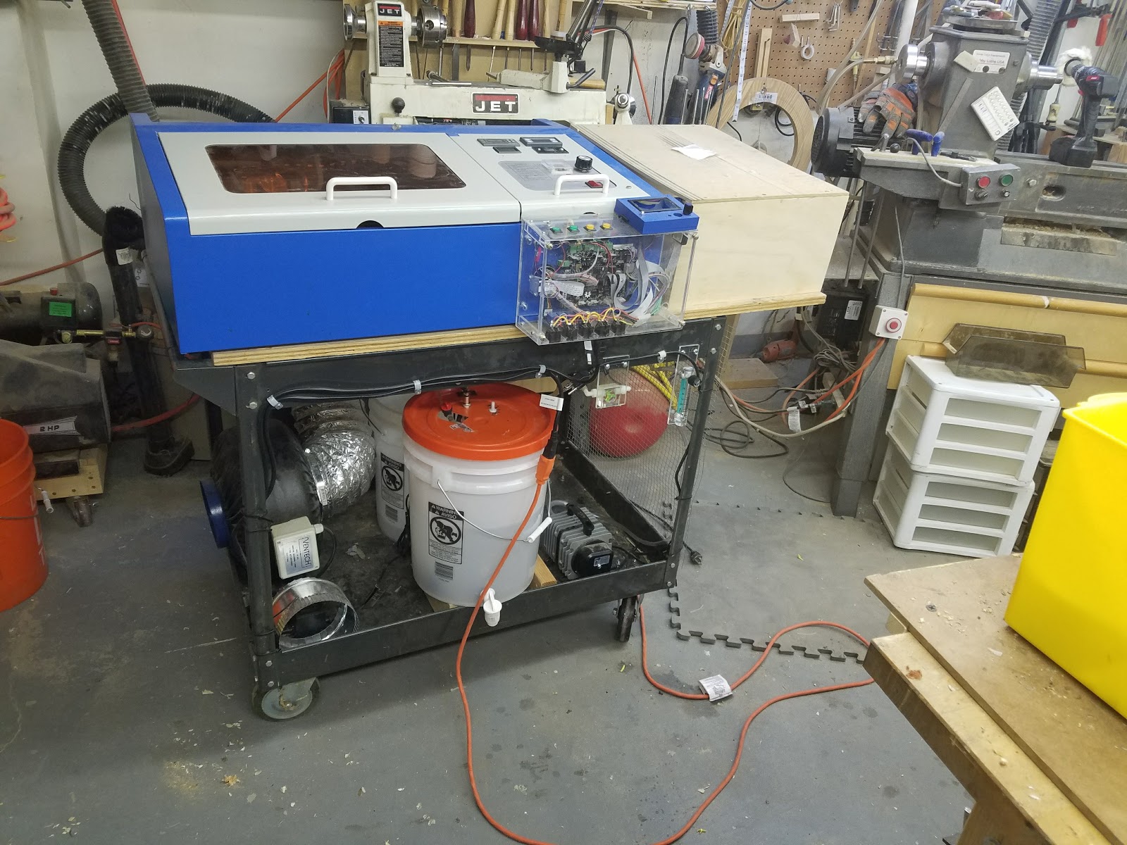
My cooling system has been mostly a hack of tubes, pipes, switches and interlocks. Improving it has for some time taken a back seat to other K40 conversion activities. I recently moved my K40 to the garage shop and decided to get rid of all the hacks and partially complete conversions. The cooling circuit was one of those on the agenda to be rebuilt.
These things bothered me about the current setup:
- The flow switch was in series with the water circuit likely reducing the coolants flow.
- The wiring was a hack and any time I had to troubleshoot the sensor wiring I had to solder and un-solder stuff.
- I had to stand on my head to get to the water bucket and its aritfacts.
- I had no visual way to tell if water was flowing other than the interlocks were not open.
- And lastly and the most annoying was the need to clear air bubbles from the laser tube at every water change.
This post details the rebuild of my cooling water and sensor systems circuits.
Donate:
Please consider donating (button to the right of this post).Your donations help fund additional research, tools and parts that I will return to the community as information.
For other information on the K40-S build use the K40-S BUILD INDEX with schematics

Yes, a disadvantage is that some coolant remains in the system after a change. I judge that amount of old coolant to be acceptable and over time I will prove it by keeping track of my waters conductivity.
The drain spigot came from Wallmart. I found it where the buckets are sold. Drill a 1" hole in the bucket about 2" up from the bottom and hand thread the spigot into the hole with a bead of "Plumbers Goo" around the flange. You can also screw a flange (its a garden thread) on the inside if you want it to be more secure. I recommend the white Wallmart buckets as you can see the water level easily.
Just in case.... I have a backup approach to the bubble problem. I added two shutoff valves in series with the input (V1) and the output (V2) of the lasers water circuit. The idea is to shut these both off and then remove the tubing from the pump to the valve. Drain and refill the bucket. Start the pump and while water is exiting push it onto V1, this essentially bleeds the input. Then turn on V1 and V2 and the cooling circuit is back to normal with no bubbles.
Valves V1 and V2 are also useful to isolate the cooling system from the bucket if you need to remove it.
The valves I found are made for fuel shutoffs in mowers. I chose them because they are inexpensive but also because they have a pretty low restriction. Most other valves narrow to a very small hole and or are very large.

Clearing Bubbles & Water Replacement
After each water change I had bubbles. I tried every form of water conditioning additives and patiently running the pump for days... nothing got rid of the bubbles. Some info on water conditioning and additives is located under Water bubble treatment.
In my case I had to lift the left side of the machine very high, more than 45 degrees and tilt the back toward the front until the bubbles would exit the laser through the hooked cooling exit of the laser tube. Not something you want to do by yourself and not a healthy for a device that has marginal optical stability anyway.
The Solution
As is often the case, the solution ended up to be simple. Just don't ever drain all the water out of the system and break the cooling circuit!
Add A Spigot
I added a drain to the bucket. The solution is to drain all but the last 1-2 inches of water out the drain. Since the pumped water exits a pipe that is in a fixed position below this level, the coolant circuit is never broken and therefore bubbles will not form when the circuit is refilled. Actually the laser tube is never refilled, the bucket is. See the circuit diagram.

The drain spigot came from Wallmart. I found it where the buckets are sold. Drill a 1" hole in the bucket about 2" up from the bottom and hand thread the spigot into the hole with a bead of "Plumbers Goo" around the flange. You can also screw a flange (its a garden thread) on the inside if you want it to be more secure. I recommend the white Wallmart buckets as you can see the water level easily.
- 5 gallon bucket
- Spigot (not the one I used but I like this one better).
The New Cooling Circuit Diagram
 |
| Water & Electrical Circuit Diagram |
Shutoff Valves V1-V2
Just in case.... I have a backup approach to the bubble problem. I added two shutoff valves in series with the input (V1) and the output (V2) of the lasers water circuit. The idea is to shut these both off and then remove the tubing from the pump to the valve. Drain and refill the bucket. Start the pump and while water is exiting push it onto V1, this essentially bleeds the input. Then turn on V1 and V2 and the cooling circuit is back to normal with no bubbles.
Valves V1 and V2 are also useful to isolate the cooling system from the bucket if you need to remove it.
The valves I found are made for fuel shutoffs in mowers. I chose them because they are inexpensive but also because they have a pretty low restriction. Most other valves narrow to a very small hole and or are very large.
Pump
Although a higher capacity pump is likely in my future I am using a Harbor Freight pump for now. I noticed that the laser tube has a pretty high impedance to flow and I am not sure that a higher capacity pump is worth the money. For now, I focused on keeping the diameter of all the tubing and fittings as large as possible. Be careful because much of the available 1/4 tubing fittings dramatically restrict flow.
Flow Switch
I did not like the way my flow switch operated. It is in serial with the water flow. I worry about the restrictions. I decided to change to a T (parallel) connected diaphragm switch. This one came from Light Objects. It mounted conveniently under the lid, tapped (with a T) off the pump's output.
I found out that the switch will not work if you put it on the output side of the system after the laser tube. There is not enough back pressure to fill the leg of the T and subsequently activate the switch's diaphragm. However, it works fine on its lowest setting when put directly at the pump's output.
Note: the screw on the backside of the diaphragm plunger is not an adjustment it is just a fastener.
I was concerned that if I placed the switch at the input there was a failure mode such that if the line between the pump and the laser opened the sensor would still see water flow and not open the interlocks. Not to worry when the line opens the backpressure decreases and the interlock opens.
The T and other piping were different sizes so I had to play with a combination of silicon tubing slipped over the fitting and some 1/4" copper tubing to make the fittings work. Tie wraps and on non-silicon materials "Plumbers Goop" secured them. Your approach and success may vary!
Thanks for the switch suggestion +Tech Bravo !
 |
| Pressure switch under the lid |
Lid Assembly
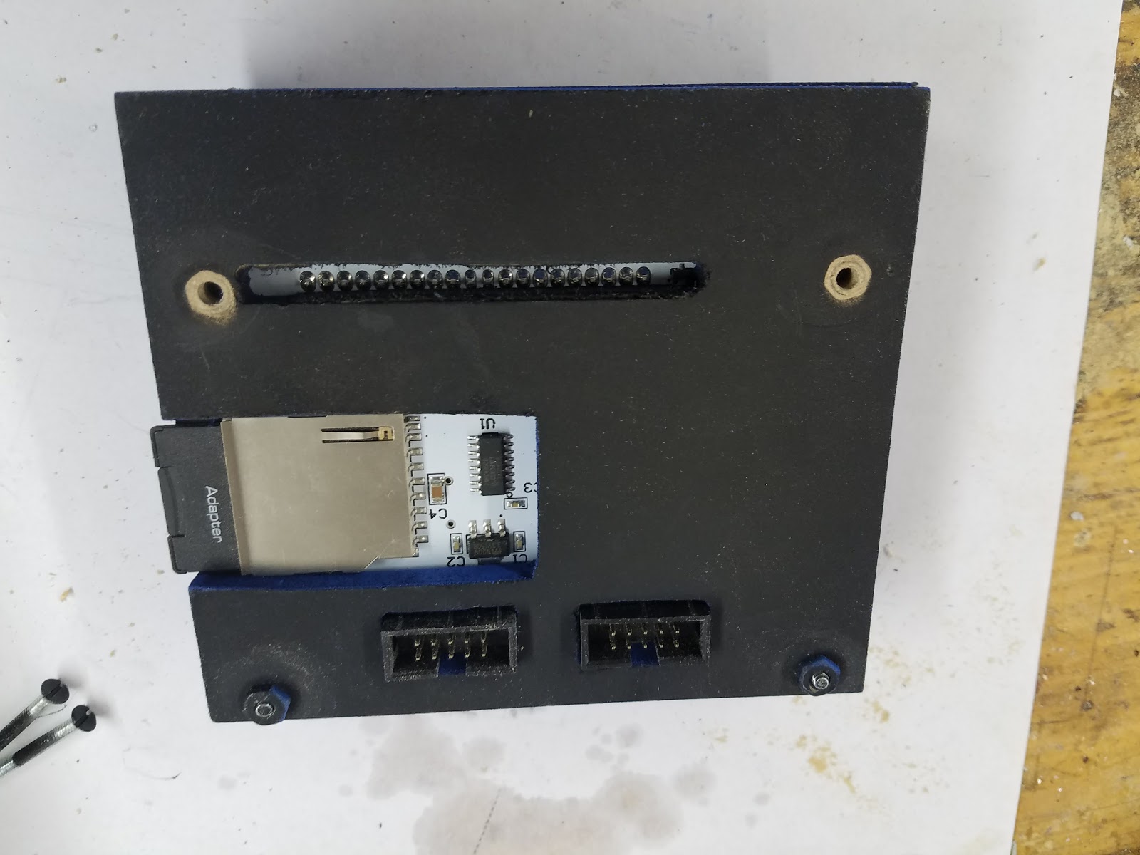
I wanted the lid and its components to be easily and modularly removed from the system and the bucket. Therefore the electrical connections for the water temperature sensor and the pressure switch were wired into a 4 pin Aviation connector.
This is the first time I have used these. They are perfect for this kind of builds as they are rugged, soldered, and keyed. A cable with one on each end now connects from the bucket to the back panel of the K40.
An output tube was made from 1/4 copper with a flange to mount it to the lid. With this setup the K40 can be totally disconnected from the lid of the bucket and the bucket lid can be disconnected from the bucket.
The output tube was affixed to the lid with a copper flange. Cut a copper fitting (1/2") down one side and then flatten it out to make a plate. Drill a 1/4" hole and solder the pipe at the right level. Screw that plate to the plastic lid with self-tapping screws.
Tie wrap the water temp sensor to the output tube so that the sensor is near the opening to get the best reading.
 |
| Output tube mounting flange |
 |
| Lid assembly |
 |
| Top of lid |
 |
| Bottom of lid |
Water Flow
I decided to put a visual water flow sensor into the output of the coolant circuit. This flow meter was mounted to an acrylic bracket and mounted to the K40's mobile frame so it was out of the way but still visible. I found out the hard way these meters work best in the orientation as shown and they must be purged of bubbles. Since we do not plan to break the coolant circuit you will only have to bleed the bubbles once. I found you can do that just by tilting this assembly clockwise.
- Water flow meter (it does not come with fittings, I used plastic 1/4 MTP fittings from HD)
- Fittings (to expensive)
Funny I just noticed that V2 is on the wrong side of the meter!
 |
| Meter glued into an acrylic bracket |

The video below shows the water flow meter in action. It also shows the new air-assist flow meter [thanks +Ned Hill ] that I also installed, but that is another post yet to come.
Enjoy, comments, suggestions, and corrections expected:
Don